

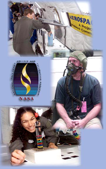
In 2001, three WCC students also participated in the NASA Reduced Gravity Student Flight Opportunities Program, where they conducted zero-g (micro-gravity) experiences on board a NASA KC-135 aircraft.
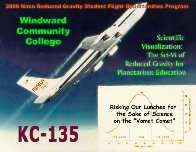
Scientific Visualization: The Sci-Vi of Reduced Gravity for Planetarium Education
A proposal submitted to the 2000 NASA Reduced Gravity Student Flight Opportunities Program For August (...November) 2000
Submitted by a Student Team from Windward Community College
Howard T. Baptiste, Jr., flight crew Sophomore, Business/Marketing
P. Kauwila Hanchett, flight crew Sophomore, Liberal Arts
Gregory J. Osterman, flight crew Sophomore, Zoology
Theresa A. Schmidt, flight crew Freshman, Education
Faculty Advisor
Dr. Joseph E. Ciotti
Professor of Physics, Astronomy & Mathematics
Aerospace Exploration Lab
Windward Community College
Table of Contents
1.0 Abstract
Educational research has long established the instructional value of incorporating visual demonstrations in science teaching. In particular, spatial and abstract concepts are more readily understood when presented with video animation. It is especially difficult for beginning physics students to grasp concepts that extrapolate our gravity-bound experience to zero-g conditions. Our proposal is to obtain high-quality video of basic physics phenomena under reduced gravity. This video, along with identical footage filmed under 1g conditions, would serve as the focus for a multi-media planetarium production ("Zero-GeeWhiz"). There have been several attempts in the past to produce such video demonstrations in the microgravity of orbital spacecraft&emdash;most notably the "Toys in Space" video project taped by astronauts aboard the Space Shuttle. While an improvement over an earlier video demonstration filmed aboard a Sky Lab mission, this project still lacks the full visual effects that are currently available through the high-tech, multi-media features of a planetarium. Through its Aerospace Exploration Lab, Windward Community College (WCC) has been a major developer of both hands-on activities and visual demonstrations in support of science education and teacher training. The underlying principal behind each is an instructional strategy which WCC terms "Scientific Visualization"&emdash;or Sci-Vi for short. WCC's Hōkūlani Planetarium, which opens Fall 2000, was designed to take full advantage of Sci-Vi. This facility houses a variety of special effects projectors that supplement the planetarium's Digistar star projector, which can project virtually any computer graphic image onto the theater's dome. Audiences can actively participate in the Sci-Vi experience through interactive controls mounted in each seat. Besides the pedagogical advantages of this multi-visual venue, this learning experience can serve as a catalyst to motivate Hawai'i's large population of minority students to pursue science education and careers.
2.0 Test Objectives
Objective 1: To produce a high-resolution video comparing selected basic physics phenomena conducted under reduced gravity and 1g. This video would serve as the primary focus for a multi-media planetarium presentation for college and lower education students enrolled in physical science courses. This presentation would address the cognitive domain by making full use of the scientific visualization features afforded by a planetarium theater.
Objective 2: To act as a catalyst to stimulate interest in science in the large population of Hawaiian and Asian-Pacific Islanders. The instructional environment of a planetarium has a unique ability to address the affective domain through the excitement it can generate through numerous high-tech, multi-media features.
back to top
3.0 Test Description
3.1 Linear and Circular Magnetic Levitation
While magnetic attraction is quite familiar to most students, a large number remain unfamiliar with its counterpart&emdash;magnetic repulsion. One basic demonstration which illustrates this phenomenon consists of several ceramic ring magnets levitating along a vertical shaft (fig. 1).
The variable spacing between each pair of magnets is a result of several forces. Magnet 1, for example, experiences a single downward force (due to gravity), while simultaneously being repelled to different degrees by all 4 magnets below it. Magnet 2, on the other hand, experiences two downward forces (one due to gravity and another due to the repulsive force of magnet 1), while it simultaneously feels 3 upward repulsive forces due to the three magnets below it. This pattern continues to the bottom magnet. What would the separation between the magnets be under microgravity conditions? This question would be proposed to the planetarium audience after viewing what occurs under 1g. The audience would then be provided different possible solutions. Selection would be made via the interactive controls at each seat. The video taped under reduced gravity during flight in the KC-135A would next be shown with supplementary visual effects generated by the planetarium projector system. A guidebook providing more detailed explanations and follow-up activities would be available to teachers. All other demonstrations described below in sections 3.2 through 3.6 would follow this same format.
An second demonstration involving magnetic levitation would use an aluminum hoop in place of the vertical shaft. Approximately 40 ring magnets would be attached to this hoop. Under 1g conditions, the magnets would settle near the bottom of the hoop in a different pattern than in the case of the vertical shaft shown in figure 1. Under microgravity conditions, it is expected that the magnetic rings should space themselves equally around the hoop.
3.2 Convection in a Rheoscopic Fluid
This demonstration will illustrate the breakdown in connection currents in a fluid under microgravity conditions. Rheoscopic fluid will be used to better view the convection currents created when a liquid-filled cylinder is heated from below (see fig. 2).

3.3 Laminar Flow in a Rheoscopic Fluid
When a fluid rotates, internal friction forces the fluid into patterns called Taylor cells. This demonstration will determine whether gravity plays any role in the creation of these cells. A cylinder filled with rheoscopic fluid will be rotated prior to entering the parabolic flight path. It is anticipated that there will be negligible effects on the cell patterns. Obtaining such a negative result from an experiment is as valuable a learning tool as that achieved from a positive result.
3.4 Internal Wave at a Liquid Interface
When liquids of different densities are allowed to mix under gravity, they will eventually separate out, leaving an interface between the two media. Under certain conditions, an internal wave can be generated at this interface. Knowledge of the way fluids mix in microgravity, for example, are critical to understand the fluid dynamics involving rocket fuel. This demonstration uses a rectangular tank containing colored mineral oil and water to explore what happens to the mixing effects and internal wave created between two different density liquids under reduced gravity conditions.
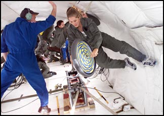
3.5 Action and Reaction: Angular Momentum
The use of gyroscopes for spin stabilization is a common practice in the aerospace industry as well as in many other technologies. Students, however, have little first-hand experience with the phenomena surrounding spinning objects. This demonstration will require the use of a portion of the width of the KC-135A. Our video camera would be mounted nearby on a tripod secured to the aircraft floor. (If relocation of our camera is not permitted, we will request filming by hand or by the on-board NASA photographer.) One of the students in our flight crew will start a small, hand-held wheel spinning during the parabolic flight path. The student will then torque the handles of the wheel to illustrate the reaction caused by the rotating wheel.
3.6 Action and Reaction: Linear Momentum
This demonstration will require the use of a portion of the width of the KC-135A. Our video camera would be mounted nearby on a tripod secured to the aircraft floor. (If relocation of our camera is not permitted, we will request filming by hand or by the on-board NASA photographer.) One the second flight, another student in our flight crew will demonstrate the principles of linear momentum by pushing a medicine ball tied to a tether line during the reduced gravity portion of the flight. The reaction force on the student will be video taped to demonstrate the principle of action and reaction. More advanced students can also use the relative speeds of the student and medicine ball to determine their relative masses. This demonstration is based on a similar experiment conducted by a previously flown flight team from Wellesley College. If their video is available and appropriate, we might request permission to include portions of that footage in our subsequently produced planetarium program.
4.0 Equipment Description
4.1 Support Stand
Other than the rotating wheel and tossed medicine ball, all equipment will be mounted on the support stand illustrated in figure 3. Each leg will be 100 cm high and constructed of a perforated angle steel frame. The legs will be bolted to two aluminum rectangular base plates, which will have 3/4-inch holes in each separated by the 20-inch bolt tie-down grid pattern required for mounting in the KC-135A. The legs will be reinforced near the bottom with additional perforated steel frames. The top of each leg will be attached to a 3/4-inch thick plywood top with standard screws. A video camera will be secured onto this top panel by a standard video mounting braces that are permanently attached to the plywood countertop. A large opening in the top is designed to permit more ambient light to enter the demonstration apparatus. Pre-drilled holes, bordering this opening in the plywood top, will allow the demonstration apparatus to be bolted to the countertop. A storage tray will also be designed into the bottom of the support stand to store the queued apparati scheduled for the current flight as well as pre-selected spare parts. The tray will be fitted with a plastic lid and reinforced with Velcro.
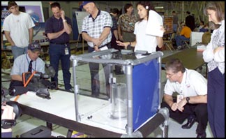
4.2 Containment Box
Figure 4 illustrates the Plexiglas box (measuring 40 cm high and 50 cm x 50 cm at the base) that will serve as a containment box in the event that fluid or other objects escape from the demonstration apparati during parabolic flight operations. The containment box is constructed of 3/4-inch wood frames, which are grooved along the inside edge to accept a 1-cm thick Plexiglas panel at all 4 sides and at the top. The bottom will be attached to a 56 cm x 56 cm Plexiglas base. A circular hole will be cut near the bottom to permit the extension of any necessary electrical cords that might be needed to operate any AC-powered apparatus installed in the containment box. When not in use, this hole will be covered over by a rubber plug. The base of the containment box will have holes around its perimeter in order to secure it to the support stand's countertop. The lid at the top of the box will be attached by Velcro strips.
4.3 MagLev Apparati
Vertical Shaft
Figure 1 illustrates the design of the vertical magnetic levitation apparatus. An aluminum vertical shaft will be permanently mounted inside a 4-cm diameter Plexiglas cylinder. 5 to 8 ceramic ring magnets will be inserted onto this shaft with like magnetic poles facing adjacent pairs. The cylinder will be filled with clear mineral oil to dampen out oscillation. The cylinder will be attached to a Plexiglas base 40 cm x 40 cm. Predrilled holes along the base's perimeter will allow the apparatus to be secured with screwed when inserted into the containment box.
Circular Hoop
Figure 5 shows the design for the circular version of the magnetic levitation apparatus. The aluminum hoop is approximately 28-cm in diameter. It is attached to an aluminum shaft that is mounted on a 40 cm x 40 cm Plexiglas base. This, like the linear shaft apparatus above, is secured inside the containment box with screws when in use.
4.4 Convection Apparatus
Figure 6 illustrates the setup of the convection current apparatus. A Plexiglas rectangular box, measuring 20 cm high by 30 cm long by 4 cm wide will be filled with rheoscopic fluid. All joints will be permanently glued together using solvent cement for joining acrylic. This box will be permanently mounted on a plywood stand, measuring 10 cm high by 34 cm long by 16 cm wide. Inside at the center of this wooden box will be an 400 W heating unit running on 110 VAC. The plywood housing will in turn be mounted on a 40 x 40 cm plywood base.
4.5 Laminar Flow Apparatus
Figure 7 illustrates the setup of the laminar flow apparatus. A 12-cm diameter Plexiglas cylinder 25 cm high will be filled with rheoscopic fluid. A top and bottom Plexiglas lid will be permanently glued together using solvent cement for joining acrylic. The 20-cm circular base of the cylinder will be screw-mounted onto a 30-cm turntable, which in turn mounted on a 40 cm x 40 cm wooden base. The cylinder will be rotated manually 5 complete turns, then stopped abruptly prior to entry into each parabolic flight.
4.6 Internal Wave Apparatus
Figure 8 illustrates the design of the apparatus for testing internal waves. A rectangular acrylic container, measuring 40 cm long by 8 cm high by 4 cm wide, will be filled with colored mineral oil and water. This container will be mounted on a plywood box, measuring 40 cm long by 10 cm high by 10 cm wide. The two boxes will be coupled at one pair of adjoining ends with a hinge. A small motor housed inside the wooden box will turn a camshaft wheel which will cause the acrylic container to oscillate and produce an internal wave. The plywood box will be mounted on a base measuring 40 cm x 40 cm.
4.7 Bike Wheel
An 18-in hand-held wheel with a solid rubber tire and wooden handle grips will be used to illustrate angular momentum and the principal of action and reaction. A video camera will be re-mounted on a standard camera tripod which will be attached to aluminum base plates with 3/4-inch holes in each so as to adhere to the 20-inch bolt tie-down grid pattern for mounting in the KC-135A.
4.8 Medicine Ball and Tether
A leather medicine ball leather weighing 3 kg will be attached to a 2-m long nylon tether, such as that used in rock climbing. The ball will be contained in a rope mesh-net that will be connected to the tether. The video camera will be re-mounted on a standard camera tripod which will be attached to aluminum base plates with 3/4-inch holes in each so as to adhere to the 20-inch bolt tie-down grid pattern for mounting in the KC-135A.
5.0 Structural Load Analysis
The strength of the solvent cement used to build the Plexiglas boxes will be tested both prior to and after construction of the boxes. Stress and vibration tests will be conducted to ensure the integrity of the joints. The brackets holding the video camera will be checked to ensure they can withstand 2.5 g's.
Our equipment exceeds neither 200 lbs per square foot nor the specified maximum 24" wide by 64" long by 60" dimensions as indicated in the JSC Reduced Gravity Program User's Guide (Doc. JSC 22803, Revision C).
6.0 Electrical Load Analysis
Our video camera will be supplied with its own 3-battery pack, permitting a minimum of 3 hours filming. We will need to access the 110 VAC power supply on-board the KC-135A to operate a 110 VAC 400W heating unit and a 110 VAC 0.1 amp electric motor.
7.0 Pressure Vessel Certification
This section is not applicable.
8.0 Check List Procedures
Pre-Flight Check
- Secure the support stand apparatus to the floor of the KC-135A
- Secure containment box to support stand
- Check power level of 3-battery pack
- Insert and rewind video tape into video camera
- Check video camera for malfunctions
- Mount and secure video camera
- Adjust camera's field of view toward primary demonstration area
- for Flight 1: Check MagLev linear apparatus, MagLev circular apparatus, internal wave apparatus and bike wheel
- for Flight 2: Check laminar flow apparatus, convection current apparatus, medicine ball
Linear MagLev Demonstration Check
- Insert and secure linear MagLev apparatus in containment box
- Start recording on video tape and vocally record time
- After 6 parabolas, remove MagLev apparatus from containment box and stow
- Vocally record time and stop video tape
Circular MagLev Demonstration Check
- Insert and secure circular MagLev apparatus in containment box
- Start recording on video tape and vocally record time
- After 6 parabolas, remove MagLev apparatus from containment box and stow
- Vocally record time and stop video tape
Convection Apparatus Check
- Insert and secure convection apparatus in containment box
- Connect power cord to KC-135A power supply
- Close and secure lid
- Start recording on video tape and vocally record time
- Turn on heater switch
- After 10 parabolas, turn off heater element, unplug power cord, remove convection apparatus from containment box and stow
- Vocally record time and stop video tape
Laminar Flow Check
- Insert and secure laminar flow apparatus in containment box
- Manually spin cylinder 5 full rotations, then stop abruptly
- Close and secure lid
- Start recording on video tape and vocally record time
- After 10 parabolas, turn switch off, disconnect AC power cord and stow apparatus
- Vocally record time and stop video tape
Internal Wave Check
- Insert and secure internal wave apparatus in containment box
- Close and secure lid
- Connect power cord to KC-135A power supply
- Start recording on video tape and vocally record time
- Switch on oscillating motor
- After 8 parabolas, turn switch off, disconnect AC power cord and stow apparatus
- Vocally record time and stop video tape
Angular Momentum Wheel Check
- Flight crew #1 moves video camera to mounting in center of aircraft
- Flight crew #2 carries wheel to center of aircraft
- Flight crew #1 starts recording on video tape and vocally records time
- Flight crew #2 begins rotation of wheel
- After 10 parabolas, stow bike wheel
- Vocally record time and stop video tape
Linear Momentum Medicine Ball Check
- Flight crew #1 moves video camera to mounting in center of aircraft
- Flight crew #2 carries medicine ball with tether to center of aircraft
- Flight crew #1 starts recording on video tape and vocally records time
- Flight crew #2 holds medicine ball at chest height with tether loop in one hand
- Flight crew #2 throws ball
- After 10 parabolas, stow ball
- Vocally record time and stop video tape
back to top
9.0 Parabolic Requirements
The following parabolic schedule takes into account the time required to set up, video tape and disassemble each demonstration.
Flight#1
Familiarization with plane 5 parabolas
Internal Wave Demonstration 8 parabolas
Linear MagLev Demonstration 6 parabolas
Circular MagLev Demonstration 6 parabolas
Angular Momentum Demonstration 10 parabolas
TOTAL: 35 parabolas
Flight#2
Familiarization with plane 5 parabolas
Laminar Flow Demonstration 10 parabolas
Convection Current Demonstration 10 parabolas
Angular Momentum Demonstration 10 parabolas
TOTAL: 35 parabolas
10.0 Post-flight Analysis
Analysis of the experimental results will be made by viewing the video recordings of each demonstration. Detailed, qualitative decriptions of the results observed under reduced gravity conditions will recorded and compared with those results obtained from identical experiments filmed earlier in Hawai'i under 1 g conditions. Quantitative results will be also be obtained for folow-up activities included in the guidebook which will accompany the planetarium program
The actual g-profile for the flight path will be obtained by using the KC-135's on-board accelerator. Our video tape will have vocal time cues indicating the start and ending of each video taping session. These times will be used when post-processing the KC-135's records.
Video images will be captured through computer video card and edited for production in our planetarium program "ZeroGeeWhiz." Other graphics and computer animations will be created based on these results to assist students in scientifically visualizing the principles behind these demonstrations as well as our experiences aboard the KC-135A.
11.0 Test Support Requirements
In-flight, we will require:
- Video and still photography provided by JSC
- A cross-section of the plane, either in front or back, so as to have room for the angular and linear momentum demonstration
12.0 Data Acquisition System
Our data acquisition system will consist of a Sony DVCAM DSR-200A digital video camera, which produces TV-broadcast quality images (fig. 9). The camera will be powered by a rechargable 3-battery pack which under full charge provides 3 hours of operating time. All video will be recorded on DVCAM tap, which permits 3 hours of continuous recording.
We have opted to eliminate a separate accelerometer for our apparati in order to fill the camera field of view with the largest image of the actual demonstration underway. The actual g-profile for the flight path will be obtained by post-processing the data recorded by KC-135's on-board accelerator. To accomplish this, the flight crew member video taping the experiment will record via the camera's microphone a vocal time mark at the start and end of each filming. These times will be used when post-processing the KC-135's records.
13.0 Test Operating Limits or Restrictions
The two fluids of different densities in the internal wave demonstration may fail to re-separate between parabolic paths. This might result in the lost of a sharp interface between the liquid with a subsequent loss of the internal wave. The demonstration will nevertheless still be able to visually illustrate how different fluids mix under reduced gravity. This demonstration is being conducted first in order to prevent any interface degradation. If another experiment were conducted prior to it, the fluids in the internal wave apparatus might become too agitated as they experienced reduced gravity while in storage.
14.0 Proposed Manifest for each Flight
|
containment box |
Plexiglas and wood frame |
|
linear MagLev apparatus |
Plexiglas, mineral oil, ceramic magnets and aluminum |
|
ciicular MagLev apparatus |
Plexiglas, ceramic magnets and aluminum |
|
laminar flow apparatus |
Plexiglas, wood and rheoscopic fluid |
|
convection current apparatus |
Plexiglas, wood and rheoscopic fluid, electric heater |
|
internal wave apparatus |
Plexiglas, wood, mineral oil, water, electric motor |
|
angular momentum apparatus |
wheel (plastic, rubber and wood) |
|
linear momentum apparatus |
medicine ball (leather and nylon) |
|
digital video camera |
DVCAM with DVCAM cassette |
|
tripod |
aluminum |
|
extra camera battery pack |
lithium |
|
fire extinguisher |
standard |
|
2 students |
flight crew |
back to top
15.0 Photographic Requirements
We will use a Sony DVCAM DSR-200A digital video camera for record our demonstrations. The camera will initially be mounted on our support stand to record our demonstrations not involving our flight crew. During the demonstrations involving our flight crew (angular and linear momerntum demonstrations), we will reposition our camera onto a tripod to be located We are requesting that both video and still shots of the two team members performing demonstrations be taken by a NASA photographer.
16.0 Hazard Analysis
Hazard 1: Fire
Description: The heater element malfunctions and causes an electrical fire.
Cause: The heater element in convection current apparatus overheats or shorts out.
Controls: The box will be constructed out of flame retardant and only treated or non-flammable materials will be used inside the box. The box is inside a containment box in order to contain any fire. We will also be carrying a standard fire extinguisher on-board.
Verification: Prior to conducting the convection current demonstration, the heater unit will be inspected and tested.
Hazard 2: Collision/Impact
Description: During transition between 0-g and pullout, flight passenger collides with equipment and is cut.
Cause: The support stand and Plexiglas boxes have sharp edges.
Controls: All Plexiglas edges will be rounded off. All metal edges will be filed down. Any remaining exposed, sharp edges will be covered with pipe insulation foam.
Verification: Prior to flight, the stand and boxes will be re-examined for exposed sharp edges. All insulation be physically checked to ensure that it is secured.
Hazard 3: Collision/Impact
Description: Bike wheel or medicine ball hits passenger.
Cause: Wheel or medicine ball is released. Tether snaps or rebounds back.
Controls: The medicine ball weighs 3 kg (6.5 lbs), which in the worse case scenario of 2.5-g would weigh 7.5 kg (16 lbs). The wheel weighs approximately the same. Both the wheel and medicine ball will be tethered and held in one hand. A high tension, rock climbing rope will be selected for the tether. The ball will be thrown at low velocities in order to maintain control. To eliminate the possibility of injury to the flight member holding the tether, the tether can be quickly released released if the ball is not in control during the high-g portion of flight.
Verification: A strength test will be conducted on the rope to ensure its ability to withstand high tensions.
Hazard 4: Structural Failure
Description: Fluid leaks or other item such as magnetic ring escapes from plexiglas box.
Cause: Joints in Plexiglas box separates.
Controls: A test will be conducted during the assembly phase to ensure that all joints are properly cemeted together and can withstand high stress. Should a fluid leak or an object escape from its Plexiglas box, it will remained confined within the containment box.
Verification: All Plexiglas joints will be inspected prior to use.
Hazard 5: Electrical Shock
Description: Passenger experiences electrical shock.
Cause: The wire to the heater element or electric motor becomes exposed while drawing current.
Controls: During assembly, all electrical wires were be checked for proper connections and insulation.
Verification: The heater and electric motor will be checked prior to flight.
17.0 Public Outreach Plans
The video obtained from this project, along with identical footage filmed under 1g conditions, will serve as the focus for a multi-media planetarium production entitled, "Zero-GeeWhiz," which will be presented at WCC's new Hōkūlani Planetarium. This program will incorporate the principal of "Scientific Visualization" (Sci-Vi) by blending the demonstration videos made prior to and during our KC-135A flight with the numerous visual special effects available in a planetarium environment. The audien will be able to vicariously experience the effects of reduced gravity as they watch the actual video along with computer animations that simulate several physical science phenomena. Furthermore, the audience will be able to actively participate in the Sci-Vi experience through interactive controls as the show moves from one demonstration to the next. A guidebook of explanations and follow-up activities will be made available to teachers visiting with their classes. More importantly, we anticipate that this planetarium program will serve as a stimulating catalyst to motivate students&emdash;especially those belonging to Hawai'i's large minority population of Hawaiian and Asian/Pacific Islander&emdash;to pursue science education and careers. We will also create a web page of our results and make our video demonstrations available as quicktime and mpg downloads via the internet.
18.0 Project Publicity
Although at this stage, we do not have a firm commitment for a participating journalist, KITV Channel 4 News is currently evaluating the feasibility of sending a news reporter.
19.0 Conclusion
The video recordings of the physical science demonstrations which we have selected were chose for their simplicity in order to appeal to students in lower education science classes as well as college courses. By incorporating these videos in a planetarium program, we will be able to maximize the impact of our outreach efforts since we anticipate an annual attendance of over 10,000 students at Windward Community College's new Hōkūlani Planertarium. This multi-media venue can take full advantage of WCC's educational efforts in promoting science literacy through "Scientific Visualization." Besides the positive effects on student understanding of basic physical science concepts, this project&emdash;through our planetarium outreach production&emdash;will serve to inspire students of all socio-economic backgrounds to expand their science education and literally reach for the stars as they consider the possibilities of a science career.